Page 5 - 10-phy-14 Current Electricity
P. 5
Experiment Study resistors in series circuit.
14.2 Date ________________
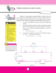
Background When two or more resistors are joined together, one after the other, the
Information circuit is called series combination of resistors. In such a combination there is
only one path for the current to flow. Fig. 14.2.1 shows the resistors R1, R2 and R3
connected in series. This type of combination has the following characteristics:
! CAUTIONS i. In a series combination, the current is the same through each
resistor.
Ÿ Connect the key to the
positive of the power ii. The total potential drop across the series combination is equal to
supply. the sum of the potential drops across all the resistors connected in
series. For n resistors, the potential difference V across the
Ÿ Connect ammeter and combination is
voltmeter according to
their polarity, i.e. the V = V1 + V2 + V3 + …………… + Vn
positive terminal of the iii. The equivalent resistance Re is equal to the sum of the resistances
meter should be
towards the positive R1 , R2 , R3 ……and Rn connected in series.
terminal of the power Re = R1 + R2 + R3 …………… + Rn
supply.
Ÿ Open the key after
every reading and close
it again before taking
the next reading.
DO YOU KNOW? Voltmeter
The bulbs connected in +V-
series have to share the
voltage of the power supply, R1 R2 R3
so such bulbs glow dimly.
- I1 I
A Ammeter Key +-
Fig. 14.2.1
+ Power Supply
Rheostat
34
14.2 Date ________________
Background When two or more resistors are joined together, one after the other, the
Information circuit is called series combination of resistors. In such a combination there is
only one path for the current to flow. Fig. 14.2.1 shows the resistors R1, R2 and R3
connected in series. This type of combination has the following characteristics:
! CAUTIONS i. In a series combination, the current is the same through each
resistor.
Ÿ Connect the key to the
positive of the power ii. The total potential drop across the series combination is equal to
supply. the sum of the potential drops across all the resistors connected in
series. For n resistors, the potential difference V across the
Ÿ Connect ammeter and combination is
voltmeter according to
their polarity, i.e. the V = V1 + V2 + V3 + …………… + Vn
positive terminal of the iii. The equivalent resistance Re is equal to the sum of the resistances
meter should be
towards the positive R1 , R2 , R3 ……and Rn connected in series.
terminal of the power Re = R1 + R2 + R3 …………… + Rn
supply.
Ÿ Open the key after
every reading and close
it again before taking
the next reading.
DO YOU KNOW? Voltmeter
The bulbs connected in +V-
series have to share the
voltage of the power supply, R1 R2 R3
so such bulbs glow dimly.
- I1 I
A Ammeter Key +-
Fig. 14.2.1
+ Power Supply
Rheostat
34