Page 9 - 10-phy-14 Current Electricity
P. 9
Experiment Study resistors in a parallel circuit.
14.3
Date ________________
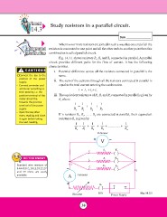
Background When two or more resistors are joined in such a way that one end of all the
Information resistors is connected to one point and all the other ends to another point then this
combination is called parallel circuit.
! CAUTIONS
Fig. 14.3.1 shows resistors R1, R2 and R3 connected in parallel. A parallel
Ÿ Connect the key to the circuit provides different paths for the flow of current. It has the following
positive of the power characteristics.
supply.
i. Potential difference across all the resistors connected in parallel is the
Ÿ Connect ammeter and same.
voltmeter according to
their polarity, i.e. the ii. The sum of the currents through all the resistors connected in parallel is
positive terminal of the equal to the total current entering the combination.
meter should be
towards the positive I = I1 + I2+ I3
terminal of the power
supply. iii. The equivalent resistance of R1, R2 and R3 connected in parallel is given by
Re where
Ÿ Open the key after
every reading and close 11 1 1
it again before taking =+ +
the next reading. Re R1 R2 R3
If n resistors R1, R2, …… Rn are connected in parallel, their equivalent
resistance Re is given by
1 = 1 + 1 + 1 + ................+ 1
Re R1 R2 R3 Rn
Voltmeter
+V-
I1 R1 K1
K2
DO YOU KNOW? I I2 R2 K3
I3
Standard wire resistors of - RR13
5.6,6.8,8.2,,10,12,18,22,27
and 39 ohms are easily A Ammeter I
available. Fig. 14.3.1
+ K +-
Rheostat Key
Power Supply
38
14.3
Date ________________
Background When two or more resistors are joined in such a way that one end of all the
Information resistors is connected to one point and all the other ends to another point then this
combination is called parallel circuit.
! CAUTIONS
Fig. 14.3.1 shows resistors R1, R2 and R3 connected in parallel. A parallel
Ÿ Connect the key to the circuit provides different paths for the flow of current. It has the following
positive of the power characteristics.
supply.
i. Potential difference across all the resistors connected in parallel is the
Ÿ Connect ammeter and same.
voltmeter according to
their polarity, i.e. the ii. The sum of the currents through all the resistors connected in parallel is
positive terminal of the equal to the total current entering the combination.
meter should be
towards the positive I = I1 + I2+ I3
terminal of the power
supply. iii. The equivalent resistance of R1, R2 and R3 connected in parallel is given by
Re where
Ÿ Open the key after
every reading and close 11 1 1
it again before taking =+ +
the next reading. Re R1 R2 R3
If n resistors R1, R2, …… Rn are connected in parallel, their equivalent
resistance Re is given by
1 = 1 + 1 + 1 + ................+ 1
Re R1 R2 R3 Rn
Voltmeter
+V-
I1 R1 K1
K2
DO YOU KNOW? I I2 R2 K3
I3
Standard wire resistors of - RR13
5.6,6.8,8.2,,10,12,18,22,27
and 39 ohms are easily A Ammeter I
available. Fig. 14.3.1
+ K +-
Rheostat Key
Power Supply
38