Page 6 - 10-phy-14 Current Electricity
P. 6
Materials Standard resistors of 8.2Ω, 10 Ω and 12 Ω of 5 watt each, variable power supply
Required (0-12V/2A), voltmeter (3V, 15V), ammeter (0.6A, 3A), key, rheostat (0-50 ohm),
connecting wires and sandpaper.
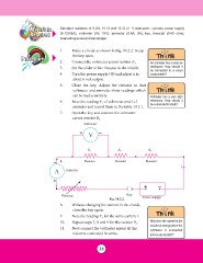
Procedure 1. Make a circuit as shown in Fig. 14.2.2. Keep
the key open.
2. Connect the voltmeter across resistor R1. An ammeter has a very low
3. Set the slider of the rheostat in the middle. resistance. How should it
be connected to a circuit
4. Turn the power supply ON and adjust it to components?
about 6 volt output.
5. Close the key. Adjust the rheostat so that
voltmeter and ammeter show readings which
can be read accurately. Voltmeter has a very high
6. Note the reading V1 of voltmeter and I of resistance. How should it
be connected to a bulb?
ammeter and record them in the table 14.2.1.
7. Open the key and connect the voltmeter
across resistor R2.
Voltmeter
+V-
R1 R2 R3
- I1 Resistor Resistor Resistor
A Ammeter I
+
+-
Rheostat Key Power Supply
Fig. 14.2.2
8. Without changing the current in the circuit,
close the key again.
9. Note the reading V2 for the same current I. Why does the current in the
10. Repeat steps 7, 8 and 9 for the resistor R3. circuit not change when the
11. Now connect the voltmeter across all the voltmeter is connected
across any resistor?
resistors connected in series.
35
Required (0-12V/2A), voltmeter (3V, 15V), ammeter (0.6A, 3A), key, rheostat (0-50 ohm),
connecting wires and sandpaper.
Procedure 1. Make a circuit as shown in Fig. 14.2.2. Keep
the key open.
2. Connect the voltmeter across resistor R1. An ammeter has a very low
3. Set the slider of the rheostat in the middle. resistance. How should it
be connected to a circuit
4. Turn the power supply ON and adjust it to components?
about 6 volt output.
5. Close the key. Adjust the rheostat so that
voltmeter and ammeter show readings which
can be read accurately. Voltmeter has a very high
6. Note the reading V1 of voltmeter and I of resistance. How should it
be connected to a bulb?
ammeter and record them in the table 14.2.1.
7. Open the key and connect the voltmeter
across resistor R2.
Voltmeter
+V-
R1 R2 R3
- I1 Resistor Resistor Resistor
A Ammeter I
+
+-
Rheostat Key Power Supply
Fig. 14.2.2
8. Without changing the current in the circuit,
close the key again.
9. Note the reading V2 for the same current I. Why does the current in the
10. Repeat steps 7, 8 and 9 for the resistor R3. circuit not change when the
11. Now connect the voltmeter across all the voltmeter is connected
across any resistor?
resistors connected in series.
35